 |
| The
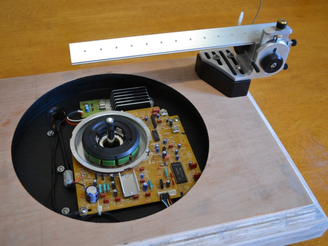
electronics and arm have been fitted, so all the threaded inserts
lined up as they should. You can see the heat sink I produced for the
regulator, this stands on 4mm brass pillars. The PCB is on 15mm x 8mm
dia Nylon pillars, you can see the harness has been soldered
direct to the connector pins at bottom right, the PCB can be removed
with the leads still attached as the cable entry slot has been made
large enough for the multi-pin connectors that attach to the PSU to fit
through. The right corner of the board tucks under the plinths top aperture,
there is just enough room to access the fixing screw. Because I
modelled the whole deck on a CAD package I was able to plan this level
of detail before any work was started. If you look at the block the arm
is sitting on, its right hand face lines up exactly with the top edge
of the chamfer in the plinth, just as it does in the earlier CAD
rendering of the proposed deck. Working with a 3D CAD model shows up
the design issues before you make the parts, so you can tweak the
design in advance. For instance, its no coincidence that the pillars
for the PCB are exactly 15mm tall which is a standard size for off the
shelf parts, I tweaked the assembly to create that height and also so I
could use standard multiples of plywood for the plinth, avoiding
unnecessary machining. I downloaded the CAD package which is a trimmed down
student version, but it still has some reasonable functionality and
most importantly was free. |
 |
 |